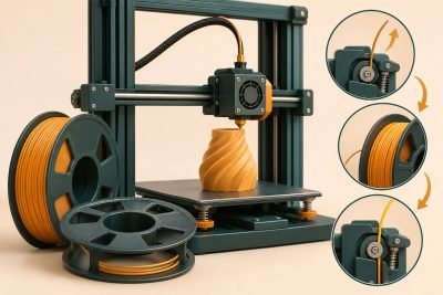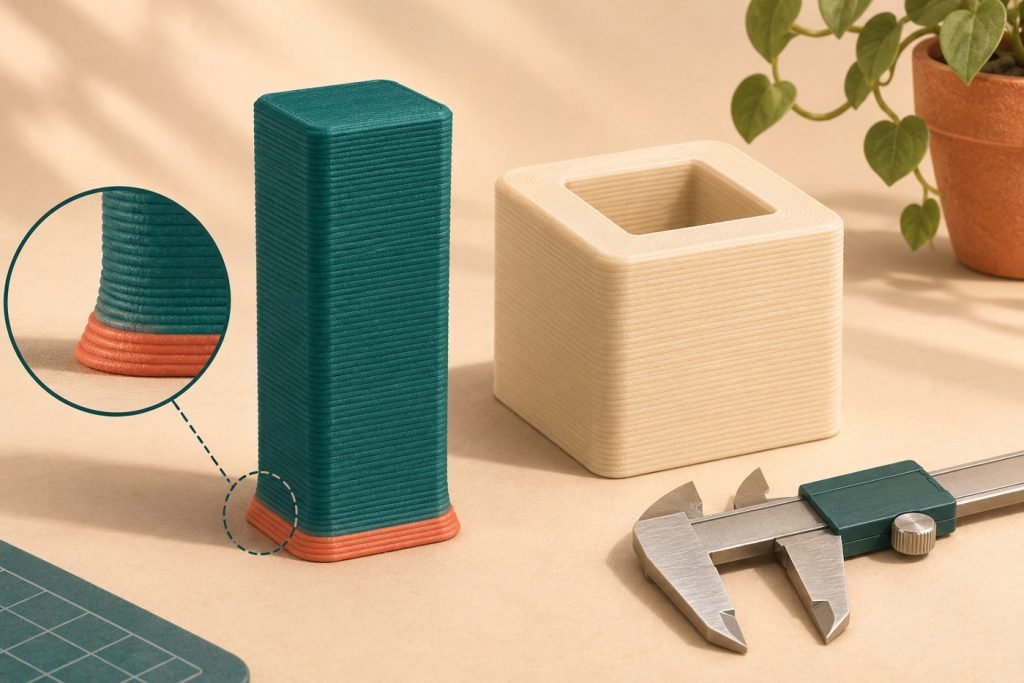
A part can measure correctly halfway up and still refuse to enter its matching recess. Check the bottom edge before shrinking the entire model: a small outward lip on the first layers is a different problem from an oversized part throughout its height.
Find where the extra width begins and ends
Let the part cool and remove it according to the plate instructions. Compare the base with a straight section above it, avoiding an intentional chamfer or rounded corner. Use the same measuring direction each time. A mating piece can reveal a fit problem, but a tight fit alone does not identify its cause.
- A thin outward lip at the bottom: a candidate for first-layer investigation.
- Similar excess width all the way up: investigate broader dimensional accuracy before changing only the base.
- A corner curving upward: follow the corner-lifting diagnosis; compensation does not flatten a warped part.
Check that the intended plate, nozzle and material profile are selected, and follow the printer’s first-layer calibration procedure. A software offset should not substitute for a visibly faulty first layer. Preserve the original profile so a small test can be reversed.
Two settings that should not be confused
| Setting | What to check |
|---|---|
| Elephant foot | Targets the lowest layers. Confirm both the distance and, where available, how many layers receive it. |
| XY size | Changes contours or holes more broadly. Use it only when the measured error calls for that wider correction. |
Raise3D’s ideaMaker documentation treats contour and hole compensation separately. Its positive contour value enlarges the outline, while a positive hole value enlarges the opening. Those signs illustrate why copying a number between differently named controls is unreliable.
Check your slicer’s behavior before printing
PrusaSlicer: first-layer shrink and thin features
Prusa’s documentation describes shrinking the first layer, with adaptive handling of thin lines. Official profiles may already enable the setting. Look at the saved value before adding another correction.
A small brim gap in preview can be intentional because the preview does not show the physical squish. Inspect the printed connection: a brim that remains detached can indicate excessive compensation. Thin junctions also deserve a closer look after changing the value.
OrcaSlicer: distance and compensated layers
The official OrcaSlicer wiki describes a positive distance that shrinks the first layer, tapering over the selected number of layers. It applies to objects directly on the plate and is skipped with a raft.
Check the documentation for your installed version. Keep the distance and layer count separate in your notes; changing both at once makes the next print harder to interpret. Inspect the lowest layers in preview and verify the real part rather than accepting a smaller preview outline as proof of a good fit.
Use a small fit test, not the whole assembly
- Choose a short section that includes the problem edge and the relevant mating feature.
- Keep its orientation, plate and material consistent with the intended job.
- Record the baseline value and the observed base-versus-upper width.
- Change one compensation control, within the slicer’s documented behavior, and inspect the preview.
- After cooling, check entry into the mating part, upper dimensions, thin details and first-layer attachment.
Do not judge the result only by whether two pieces can now be forced together. The useful outcome is a clean fit without sacrificing the base or moving the error into a fragile detail. If each correction needs to grow substantially, return to calibration and the selected profile rather than treating compensation as an unlimited repair.
Save the correction that solves the edge
Keep a note of the printer, plate, material, layer settings and compensation used for the successful test. That makes the result reusable without pretending it applies to every spool and geometry.
The lip is gone and the part fits
Use the recorded profile for the full part, then inspect the same edge after cooling. Preserve the small test as a reference when changing a relevant setup condition.
The base fits, but the rest still does not
Measure the remaining error separately. Do not keep increasing the base correction to solve a whole-part dimension or a mismatched design allowance.